Kubernetes Networking: How to Write Your Own CNI Plug-in with Bash

Exploring the internals of Kubernetes networking
When I was preparing Kubernetes training courses, I found an area that induced a lot of interest, but at the same time, was very difficult to explain—the internals of Kubernetes networking. Everybody wants to know so much:
- How pods deployed to different physical nodes can communicate directly with each other using IP addresses allocated from a single subnet
- How Kubernetes services work
- How load balancing is implemented
- How network policies are implemented
- How much overhead Kubernetes overlay networking adds
It is difficult to answer all of these questions, because in order to really understand them you need to be aware of various low-level networking concepts and tools—such as NAT, the OSI network layers, IPtables, VFS, VLANS, and more. People can get especially puzzled when they need to choose one of the available networking solutions for Kubernetes. As you can see, the list is a large one.
Most of the mentioned solutions include container network interface (CNI) plug-ins. These are the cornerstones of Kubernetes networking, and it is essential to understand them to make an informed decision which networking solution to chose. It is also useful to know some details about the internals of your preferred networking solution. This way, you will be able to choose what Kubernetes networking features you need, analyze networking performance / security / reliability, and troubleshoot low-level issues.
The purpose of this blog post is to help you understand Kubernetes networking in greater detail and assist you with all of the above-mentioned tasks. So, here is the plan:
- We will start with the discussion of the Kubernetes network model and how CNI plug-ins fit into it.
- Then, we will try to write a simple CNI plug-in responsible for implementing a Kubernetes overlay network, as well as for allocating and configuring network interfaces in pods.
- We will also deploy a Kubernetes cluster and configure it to use our plug-in.
- Along the way, we will discuss all the relevant networking concepts required to understand how the plug-in works.
Now let’s jump directly to the fist topic.
The model of a Kubernetes network
The main idea behind the design of the Kubernetes network model is that you should be able to directly move your workload from virtual machines (VMs) to Kubernetes containers without any changes to your apps. This imposes three fundamental requirements:
- All the containers can communicate with each other directly without NAT.
- All the nodes can communicate with all containers (and vice versa) without NAT.
- The IP that a container sees itself as is the same IP that others see it as.
The main challenge in implementing these requirements is that containers can be placed to different nodes. It is relatively easy to create a virtual network on a single host (what Docker does), but spreading this network across different virtual machines or physical hosts is not a trivial task. The following diagram illustrates how the Kubernetes network model is usually implemented.
 Example of a typical Kubernetes network
The idea is that we allocate a subnet for each container host and then set up some kind of routing between the hosts to forward container traffic appropriately. This is something you will be able to implement by yourself after reading this post.
CNI plug-ins
Another problem with the Kubernetes network model is that there is no single standard implementation of it. Instead, the preferred implementation greatly depends on an environment where your cluster is deployed. That’s why the Kubernetes team decided to externalize the approach and redirect the task of implementing the network model to a CNI plug-in.
A CNI plug-in is responsible for allocating network interfaces to the newly created containers. Kubernetes first creates a container without a network interface and then calls a CNI plug-in. The plug-in configures container networking and returns information about allocated network interfaces, IP addresses, etc. The parameters that Kubernetes sends to a CNI plugin, as well as the structure of the response must satisfy the CNI specification, but the plug-in itself may do whatever it needs to do its job.
Now, when you get the basic understanding of the CNI plug-ins, we shall proceed with the investigation of the CNI plug-in interface and implementation of our own one. Before we are able to do this, we need to deploy a test cluster to experiment with.
Using kubeadm to deploy Kubernetes
Developed by the Kubernetes team, kubeadm can be used to configure and run Kubernetes components on a virtual machine or a physical host. There are many Kubernetes installers, but kubeadm is the most flexible one as it allows the use of your own network plug-in.
Before working with kubeadm, we must provision and configure VMs that will constitute our Kubernetes cluster. Because I wanted to make this guide easily reproducible, I decided to choose a managed IaaS platform for this task, such as Google Cloud Platform (GCP). If you want to follow this guide and you don’t have a GCP account, you can easily register a free trial account. It comes with a $300 credit, which is more than enough for this guide.
To learn more about kubeadm, check out the official documentation.
Preparing the GCP infrastructure
With a GCP account ready, the first thing you need to do is open the Cloud Shell. Cloud Shell is a VM that is automatically created for you by GCP. It already contains a lot of useful tools, such as the gcloud CLI, and allows you to issue gcloud commands without authentication. You can learn how to open the Cloud Shell from the official guide.
Next, you have to create a new GCP network.
$ gcloud compute networks create k8s
This command creates a new GCP network and allocates a subnet in each of the GCP regions. It also creates some default routes to direct traffic between the created subnets and redirect all the external traffic to the default Internet gateway. You can examine the created network, subnets, and routes at “VPC network -> VPC networks” and “VPC network -> Routes” pages.
Note that you use the default network instead of creating a new one, though having the same infrastructure as in this tutorial prevents you from unexpected surprises.
By default, the GCP firewall allows only egress traffic, so if you want to reach your network from the outside, you must create some firewall rules. The following command creates a firewall rule to open all the ports for all the protocols on all VMs in the Kubernetes network. (Yes, I know that it is terribly insecure, but it is okay for a few simple experiments.)
$ gcloud compute firewall-rules create k8s-allow-all \
    --network k8s \
    --action allow \
    --direction ingress \
    --rules all \
    --source-ranges 0.0.0.0/0 \
    --priority 1000
Now we can start creating our cluster—the simplest possible one. For the purpose, we just need a single master VM and a single worker VM. We can create both VMs using the following two commands:
$ gcloud compute instances create k8s-master \
    --zone us-central1-b \
    --image-family ubuntu-1604-lts \
    --image-project ubuntu-os-cloud \
    --network k8s \
    --can-ip-forward
$ gcloud compute instances create k8s-worker \
    --zone us-central1-b \
    --image-family ubuntu-1604-lts \
    --image-project ubuntu-os-cloud \
    --network k8s \
    --can-ip-forward
Here, we are just creating two VMs (k8s-master and k8s-worker) from the Ubuntu v16.04 image. The important parameter here is --can-ip-forward. This parameter configures IP forwarding on the network interface of a VM, allowing it to receive and forward network packets that have different destination IP address from its own IP address. This is a requirement, because each VM should accept packets with the destination IP set to a container IP rather then an IP of a virtual machine.
Note that alternatively you can enable IP forwarding on a VM using the following command: sysctl -w net.ipv4.ip_forward=1.
Installing Kubernetes with kubeadm
After successfully creating both master and working VMs, you have to SSH to each of them. In GCP, you can SSH to a VM just by clicking on the SSH button on the “Compute Engine -> VM instances” page. Consult with the official docs for more details.
Next, you have to execute the following sequence of commands on both a master and a worker.
- Install some prerequisite packages
$ sudo apt-get update
$ sudo apt-get install -y docker.io apt-transport-https curl jq nmap iproute2
The most important package here is Docker as Kubernetes uses it under the hood to run containers.
- Install kubeadm, kubelet, and kubectl
- kubeadm. The tool that we will be using to run and configure all Kubernetes components.
- kubelet. The primary Kubernetes node agent. It talks to Docker and runs pods on a node. All the other Kubernetes components (such as an API server, etcd, kube-proxy, etc.) are run as pods by kubelet.
- kubectl. The Kubernetes CLI, which we use to issue commands to the Kubernetes API.
$ sudo su
$ curl -s https://packages.cloud.google.com/apt/doc/apt-key.gpg | apt-key add -
$ cat > /etc/apt/sources.list.d/kubernetes.list <<EOF
deb http://apt.kubernetes.io/ kubernetes-xenial main
EOF
This command installs three binaries:
Next, we need to start the cluster. To do so, execute the following command only from the master VM:
$ sudo kubeadm init --pod-network-cidr=10.244.0.0/16
This command does the following:
- Creates the
systemdservice for kubelet and starts it. - Generates manifest files for all Kubernetes system components and configures kubelet to run them. The system components manifests are ordinary Kubernetes YAML files, which you usually use with kubectl. You can find them in the
/etc/kubernetes/manifests/folder. - Most importantly, it configures Kubernetes to use the
10.244.0.0/16CIDR range for the pod overlay networking. For now, this value isn’t used by anybody, it is just stored in the etcd database for later use.
The command below generates a lot of output. At the end of the output, you should see the command, which you may use to join the newly created cluster. It should look like this:
You can now join any number of machines by running the following on each node
as root:

  kubeadm join 10.128.0.2:6443 --token 4s3sqa.z0jeax6iydntib5b --discovery-token-ca-cert-hash sha256:ac43930987f2c40386a172fe796fd22d905480671959d65044d66c1180c39f13
Now, copy the generated command and execute it on the worker VM. This command is similar to the previous one, but instead of configuring and running system components, it instructs the kubelet on the worker VM to connect to the previously deployed API server and join the cluster.
Testing the cluster
Now, it’s time to check whether our cluster is working properly. The first thing we need to do is to configure kubectl to connect to the newly created cluster. In order to do this, run the following commands from the master VM:
$ mkdir -p $HOME/.kube
$ sudo cp -i /etc/kubernetes/admin.conf $HOME/.kube/config
$ sudo chown $(id -u):$(id -g) $HOME/.kube/config
Now, you should be able to use kubectl from the master VM. Let’s use the kubectl get nodes command to check the status of the cluster nodes.
$ kubectl get nodes NAME STATUS ROLES AGE VERSION k8s-master NotReady master 25m v1.11.1 k8s-worker NotReady9s v1.11.1
As you can see from the output, both master and worker nodes are currently in the “NotReady” state. This is expected, because we haven’t configured any networking plug-in yet. If you try to deploy a pod at this time, your pod will forever hang in the “Pending” state, because the Kubernetes schedule will not be able to find any “Ready” node for it. However, kubelet runs all the system components as ordinary pods. How, then, was it able to do so if the nodes are not ready?
The answer is that neither of the system components is deployed to the pod overlay network—all of them use the host network instead. If you check the definition of any of the system components in the /etc/kubernetes/manifests/ folder, you will see that all of them have the hostNetwork: true property in their spec. The result is that all of the system components share the network interface with the host VM. For these pods, we don’t need any networking plug-in.
Configuring a CNI plug-in
Now we’re at the interesting part. We are going to deploy our custom CNI plugin to both master and worker VMs and see how it works. But before we do this, what subnets are allocated from the pod network range to both master and worker nodes? We can find it out using the following two commands:
$ kubectl describe node k8s-master | grep PodCIDR
PodCIDR:                     10.244.0.0/24

$ kubectl describe node k8s-worker | grep PodCIDR
PodCIDR:                     10.244.1.0/24
As you can see from the output, the whole pod network range (10.244.0.0./16) has been divided into small subnets, and each of the nodes received its own subnets. This means that the master node can use any of the 10.244.0.0–10.244.0.255 IPs for its containers, and the worker node uses 10.244.1.0–10.244.1.255 IPs.
If you don’t understand how I made this calculations or are not familiar with the CIDR range notation, you can read this article.
Now, we are ready to start configuring our plug-in. The first thing you should do is create the plug-in configuration. Save the following file as /etc/cni/net.d/10-bash-cni-plugin.conf.
{
        "cniVersion": "0.3.1",
        "name": "mynet",
        "type": "bash-cni",
        "network": "10.244.0.0/16",
        "subnet": "<node-cidr-range>"
}
This must be done on both master and worker nodes. Don’t forget to replace <node-cidr-range> with 10.244.0.0/24 for the master and 10.244.1.0./24 for the worker. It is also very important that you put the file into the /etc/cni/net.d/ folder. kubelet uses this folder to discover CNI plug-ins.
The first three parameters in the configuration (cniVersion, name, and type) are mandatory and are documented in the CNI specification. cniVersion is used to determine the CNI version used by the plugin, name is just the network name, and type refers to the file name of the CNI plug-in executable. The network and subnet parameters are our custom parameters, they are not mentioned in the CNI specification, and later we will see how exactly they are used by the bash-cni network plug-in.
The next thing to do is prepare a network bridge on both master and worker VMs. The network bridge is a special device that aggregates network packets from multiple network interfaces. Later, whenever requested, our CNI plug-in will add network interfaces from all containers to the bridge.
This allows containers on the same host to freely communicate with each other. The bridge can also have its own MAC and IP addresses, so each container sees the bridge as another device plugged into the same network. We reserve the 10.244.0.1 IP address for the bridge on the master VM and 10.244.1.1 for the bridge on the worker VM. The following commands can be used to create and configure the bridge with the cni0 name:
$ sudo brctl addbr cni0
$ sudo ip link set cni0 up
$ sudo ip addr add <bridge-ip>/24 dev cni0
These commands create the bridge, enable it, and then assign an IP address to it. The last command also implicitly creates a route, so that all traffic with the destination IP belonging to the pod CIDR range, local to the current node, will be redirected to the cni0 network interface. (As mentioned before, all the other software communicates with a bridge as though it were an ordinary network interface.) You can view this implicitly created route by running the ip route command from both master and worker VMs:
$ ip route | grep cni0
10.244.0.0/24 dev cni0  proto kernel  scope link  src 10.244.0.1

$ ip route | grep cni0
10.244.1.0/24 dev cni0  proto kernel  scope link  src 10.244.1.1
Now, let’s create the plug-in itself. The plug-in’s executable file must be placed in the /opt/cni/bin/ folder, its name must be exactly the same as the type parameter in the plug-in configuration (bash-cni), and its contents can be found in this GiHub repo. (After you put the plug-in in the correct folder, don’t forget to make it executable by running sudo chmod +x bash-cni.) This should be done on both master and worker VMs.
The /opt/cni/bin folder stores all the CNI plug-ins. It contains a lot of default plug-ins, but we are not going to use them now, and we will discuss them later.
Now, let’s examine the plug-in’s source code. I won’t copy it here, instead you can open it in a separate browser window, and I will guide you through this code and explain its most important parts. The script starts with the following two lines:
exec 3>&1 # make stdout available as fd 3 for the result
exec &>> /var/log/bash-cni-plugin.log
Here, we redirect both stdin and stderr to a file and preserve the original stdout file descriptor as &3. This is required, because all CNI plug-ins are expected to read their input and write output using stdin and stdout. So, you can tail /var/log/bash-cni-plugin.log to see the logs of the plug-in, and the plug-in also uses 'echo “” >&3' whenever it needs to output something to the original stdout.
Let’s skip the allocate_ip function for now and take a look at the main switch case.
case $CNI_COMMAND in
ADD)
    …
DEL)
    …
GET)
    …
VERSION)
    …
esac
As you might infer from this definition, our CNI plug-in supports four commands—ADD, DEL, GET, and VERSION. The caller of a CNI plug-in (kubelet in our case) must initialize the CNI_COMMAND environment variable, which contains the desired command. The most important command is ADD, it is executed each time after a container is created, and it is responsible for allocating a network interface to the container. Let’s take a look how it works.
The command starts with retrieving the needed values from the plug-in configuration.
    network=$(echo "$stdin" | jq -r ".network")
    subnet=$(echo "$stdin" | jq -r ".subnet")
    subnet_mask_size=$(echo $subnet | awk -F  "/" '{print $2}')
When this command is executed, stdin contains exactly the same content as we put into the plug-in configuration (/etc/cni/net.d/10-bash-cni-plugin.conf). Here, we are getting values of the network and subnet variables. We also parse the subnet mask size. For the 10.244.0.0/24 subnet, the size will be 24.
Next, we allocate an IP address for the container.
    all_ips=$(nmap -sL $subnet | grep "Nmap scan report" | awk '{print $NF}')
    all_ips=(${all_ips[@]})
    skip_ip=${all_ips[0]}
    gw_ip=${all_ips[1]}
    reserved_ips=$(cat $IP_STORE 2> /dev/null || printf "$skip_ip\n$gw_ip\n") # reserving 10.244.0.0 and 10.244.0.1
    reserved_ips=(${reserved_ips[@]})
    printf '%s\n' "${reserved_ips[@]}" > $IP_STORE
    container_ip=$(allocate_ip)
First, we create a list of all the available IPs (all_ips) using the nmap program. Then, we read the list of IPs that are already taken (reserved_ips) from the /tmp/reserved_ips file (the IP_STORE variable points to this file). We always skip the first IP in the subnet (10.244.0.0) and assume that the next IP (10.244.0.1) will be a gateway for all containers. Remember, that the cni0 bridge will be our gateway, and we already assigned the 10.244.0.1 and 10.244.1.1 IP addresses to the bridges on the master and worker VMs.
Finally, we call the allocate_ip function, which just iterates over all_ips and reserved_ips, finds the first non-reserved IP, and updates the /tmp/reserved_ips file. This is the job that is usually done by the IPAM (IP address management) CNI plug-ins. We allocated the IP address exactly in the same way as host-local IPAM CNI plug-in does it (though, definitely, our implementation is very simplified). There are other possible ways of allocating IP addresses that include, for example, the allocation from a DHCP server.
The next two lines might look strange to you.
    mkdir -p /var/run/netns/
    ln -sfT $CNI_NETNS /var/run/netns/$CNI_CONTAINERID
The CNI spec tells the caller (in our case, kubelet) to create a network namespace and pass it in the CNI_NETNS environment variable. Here, we are creating a symlink that points to the network namespace and is located in the /var/run/netns/ folder (this is something that the ip netns tool assumes). After those commands are executed, we will be able to access the CNI_NETNS namespace using the ip netns $CNI_CONTAINERID command.
Then, we create a pair of network interfaces.
    rand=$(tr -dc 'A-F0-9' < /dev/urandom | head -c4)
    host_if_name="veth$rand"
    ip link add $CNI_IFNAME type veth peer name $host_if_name
The interfaces are created as an interconnected pair. Packages transmitted to one of the devices in the pair are immediately received on the other device. CNI_IFNAME is provided by the caller and specifies the name of the network interface that will be assigned to the container (usually, eth0). The name of the second network interface is generated dynamically.
The second interface remains in the host namespace and should be added to the bridge. That is something we are about to do in the next two lines.
    ip link set $host_if_name up
    ip link set $host_if_name master cni0
This interface will be responsible for receiving network packets that appear in the bridge and are intended to be sent to the container.
Let me pause for a moment and explain the general idea behind bridging. Here, are some analogies I found useful:
- A bridge is analogous to a network switch.
- A container is analogous to a device that we plug in to the switch.
- A network interface pair is analogous to a wire-one end we plug into a device and another to the network switch.
Any device will always have an IP address, and we will also allocate an IP for the container network interface. The port where we plug in the other end of the wire doesn’t have its own IP, and we don’t allocate an IP for the host interface either. However, a port in a switch always has its own MAC address (check this StackExchange thread if you are curious why it is the case), and similarly our host interface has a MAC.
A network switch, as well as a bridge, are both holding a list of MAC addresses connected to each of their ports. They use this list to figure out which port they need to forward an incoming network package. This way, they prevent flooding everybody else with unnecessary traffic. Some switches (layer 3 switches) can assign an IP to one of their ports and use this port to connect to the external networks. That is something we are doing with our bridge, as well. We’ve configured an IP on the bridge, which all the containers will use as their gateway to communicate with the outside world.
Okay, now let’s go back to our script. The next step is more or less obvious—we need to configure the container interface.
    ip link set $CNI_IFNAME netns $CNI_CONTAINERID
    ip netns exec $CNI_CONTAINERID ip link set $CNI_IFNAME up
    ip netns exec $CNI_CONTAINERID ip addr add $container_ip/$subnet_mask_size dev $CNI_IFNAME
    ip netns exec $CNI_CONTAINERID ip route add default via $gw_ip dev $CNI_IFNAME
First, we move the interface to the new network namespace. (After this step, nobody in the host namespace will be able to communicate directly with the container interface. All communication must be done only via the host pair.) Then, we assign the previously allocated container IP to the interface and create a default route that redirects all traffic to the default gateway, which is the IP address of the cni0 bridge).
That’s it. All configuration is done now. The only thing left is to return the information about the created network interface to the caller. This is something that we are doing in the last statement of the ADD command. (Note, how we are using the &3 descriptor to print the result to the original stdout.)
The other three CNI commands are much simpler and are not so important for us. The DEL command just removes the IP address of the container from the reserved_ips list. Note that we don’t have to delete any network interfaces, because they will be deleted automatically after the container namespace will be removed. GET is intended to return the information about some previously created container, but it is not used by kubelet, and we don’t implement it at all. VERSION just prints the supported CNI versions.
Testing the plugin
Now, if you execute the kubectl get node command, you can see that both nodes should go to the “Ready” state. So, let’s try to deploy an application and see how it works. But before we’re able to do this, we should “untaint” the master node. By default, the scheduler will not put any pods on the master node, because it is “tainted.” But we want to test cross-node container communication, so we need to deploy some pods on the master, as well as on the worker. The taint can be removed using the following command.
$ kubectl taint nodes k8s-master node-role.kubernetes.io/master-
node/k8s-master untainted
Next, let’s use this test deployment to validate our CNI plug-in.
$ kubectl apply -f https://raw.githubusercontent.com/s-matyukevich/bash-cni-plugin/master/01_gcp/test-deployment.yml
Here, we are deploying four simple pods. Two goes on the master and the remaining two on the worker. (Pay attention to how we are using the nodeSelector property to tell the pod, where it should be deployed.) On both master and worker nodes, we have one pod running NGINX and one pod running the sleep command. Now, let’s run kubectl get pod to make sure that all pods are healthy and then get the pods IP addresses using the following command:
$ k$ kubectl describe pod | grep IP
IP:                 10.244.0.4
IP:                 10.244.1.3
IP:                 10.244.0.6
IP:                 10.244.1.2
In your case, the result might be different.
Next, you have to get inside inside the bash-master pod.
$ kubectl exec -it bash-master bash
From inside of the pod, you can ping various addresses to verify network connectivity. My result was as follows.
$ ping 10.128.0.2 # can ping own host
PING 10.128.0.2 (10.128.0.2) 56(84) bytes of data.
64 bytes from 10.128.0.2: icmp_seq=1 ttl=64 time=0.110 ms

$ ping 10.128.0.3 # can’t ping different host
PING 10.128.0.3 (10.128.0.3) 56(84) bytes of data.

$ ping 10.244.0.6 # can’t ping a container on the same host
PING 10.244.0.6 (10.244.0.6) 56(84) bytes of data.

$ ping 10.244.1.3 # can’t ping a container on a different host
PING 10.244.1.3 (10.244.1.3) 56(84) bytes of data.

$ ping 108.177.121.113 # can’t ping any external address
PING 108.177.121.113 (108.177.121.113) 56(84) bytes of data.
As you can see, the only thing that actually works is a container to host communication. There’s still a lot of work for us to do.
Fixing container-to-container communication
When I first saw this result, I was very puzzled. While we haven’t done anything for cross-host communication and for external access to work, container-to-container communication on the same host should work for sure! So, I spent half a day investigating different properties of bridges and virtual network interfaces and sniffing the Ethernet traffic between containers using tcpdump. However, the issue appears to be completely unrelated to our setup. In order to explain it, let me first show you the content of the iptables FORWARD chain.
$ sudo iptables -S FORWARD
-P FORWARD DROP
-A FORWARD -m comment --comment "kubernetes forwarding rules" -j KUBE-FORWARD
-A FORWARD -j DOCKER-ISOLATION
-A FORWARD -o docker0 -j DOCKER
-A FORWARD -o docker0 -m conntrack --ctstate RELATED,ESTABLISHED -j ACCEPT
-A FORWARD -i docker0 ! -o docker0 -j ACCEPT
-A FORWARD -i docker0 -o docker0 -j ACCEPT
Here, you can see all the rules in the FORWARD chain. This very chain is applied to all the packets that instead of being passed to some local process are forwarded elsewhere. (When it comes to the iptable rules, a Linux kernel treats interfaces in non-root network namespaces as if they were external.) Then you may ask, why do the iptable rules are applied to the container-container traffic at all, even if this traffic should not cross the bridge? This is a special Linux feature, which you can inspect more closely here. You may also wonder why is it possible for us to ping the host machine from the container? In this case, the destination of the request is local to the host, and iptables applies the INPUT chain to the request instead of the FORWARD chain.
Now, if you carefully examine the content of the FORWARD chain and the nested chains (KUBE-FORWARD, DOCKER-ISOLATION, and DOCKER), you will see that there is no single rule that can be applied to a request coming from one container to another. In this case, the default chain policy—DROP—is applied. If you are interested, the default chain policy was set by Docker to enhance security.
In order to fix the issue, we need to apply additional forwarding rules that will allow to freely forward traffic inside the whole pod CIDR range. You should execute the two commands below on both master and worker VMs. This should fix the issues with communication between containers located at the same host.
$ sudo iptables -t filter -A FORWARD -s 10.244.0.0/16 -j ACCEPT
$ sudo iptables -t filter -A FORWARD -d 10.244.0.0/16 -j ACCEPT
Fixing external access using NAT
The fact that our container can’t reach the Internet should be no surprise for you. Our containers are located in a private subnet (10.244.0.0/24). Whenever a network package comes outside of a container, it will have source IP that belongs to this subnet. Due to the fact that the subnet is private, the router will drop this packet when it tries to reach the Internet. And even if it doesn’t, and the packet successfully reaches its destination, there will be no way to send a response back to the 10.244.0.X address.
In order to fix this, we should set up a network address translation (NAT) on the host VM. NAT is a mechanism that replaces a source IP address in the outcoming package with the IP address of the host VM. The original source address is stored somewhere else in the TCP packet. When the response arrives to the host VM, the original address is restored, and a package is forwarded to the container network interface. You can easily setup NAT using the following two commands:
$ sudo iptables -t nat -A POSTROUTING -s 10.244.0.0/24 ! -o cni0 -j MASQUERADE
$ sudo iptables -t nat -A POSTROUTING -s 10.244.1.0/24 ! -o cni0 -j MASQUERADE
The first command should be executed on the master VM, and the second on the worker. Pay attention that here we are NATing only packages with the source IP belonging to the local pod subnet, which are not meant to be sent to the cni0 bridge. MASQUERADE is an iptables target, which can be used instead of the SNAT target (a source NAT), when the external IP of the inet interface is not known at the moment of writing the rule.
After you set up NAT, you should be able to access external addresses, as well as other VMs, in the cluster.
Communication between containers on different VMs
Finally, there is only one issue left. Containers on different VMs can’t talk to each other. If you think about it, this makes a perfect sense. If we are sending a request from the 10.244.0.4 container to the 10.244.1.3 container, we never specified that the request should be routed through the 10.128.0.3 VM. Usually, in such cases, we can rely on the ip route command to setup some additional routes for us. If we carried out this experiment on some bare-metal servers directly connected to each other, we could do something like this:
$ ip route add 10.244.1.0/24 via 10.128.0.3 dev ens4 # run on master
$ ip route add 10.244.0.0/24 via 10.128.0.2 dev ens4 # run on worker
This, however, requires the direct layer 2 connectivity between VMs. In GCP, the above-listed commands are not going to work. Instead, we can rely on some native GCP features to set up routing for us. Just execute the following two commands from the Cloud Shell VM:
$ gcloud compute routes create k8s-master --destination-range 10.244.0.0/24 --network k8s --next-hop-address 10.128.0.2

$ gcloud compute routes create k8s-worker --destination-range 10.244.1.0/24 --network k8s --next-hop-address 10.128.0.3
The first command creates a route in GCP to forward all packages with the destination IP from the 10.244.0.0/2 range to the master VM (10.128.0.2). The second command does the same thing for the worker VM. After this, containers located on different VMs should be able to communicate.
Now, all types of communication should work just fine. As a final step, I want you to take a final look at the Kubernetes networking solution we’ve just implemented.
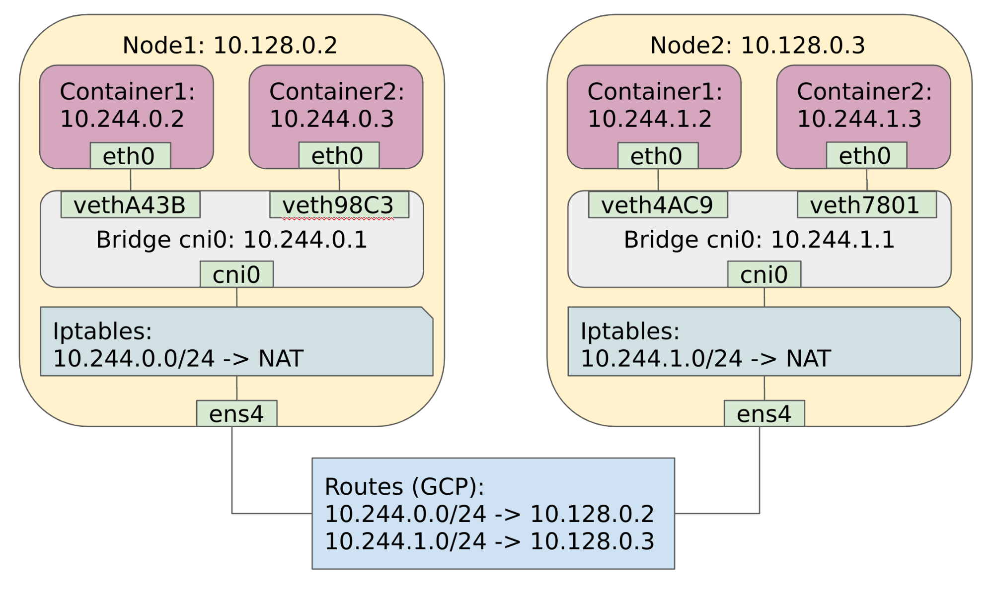 The Kubernetes network after configuration
Conclusion
We have done a great job writing our own CNI plug-in and implementing it into a Kubernetes cluster, but still our plug-in is far from being perfect. It doesn’t cover a lot of scenarios, and we haven’t discussed a lot of important details, related to the Kubernetes networking. The following list contains items that, from my point of view, would be nice to discuss and implement:
- In the real world, nobody writes a CNI plug-in from scratch like we did, everybody utilizes default CNI plug-ins instead and redirects all the job to them. We can rewrite our plug-in to do so, as well.
- We can replace our IP management with some of the host-local ipam plug-ins.
- We can also replace the rest of our plug-in with the bridge CNI plug-in. It is actually working in exactly the same way as our own one.
- We did a lot of manual work in order to prepare both master and worker VMs. Real CNI plug-ins, for instance, flanell, usually rely on a special agent to do that. It would be nice to examine how it works.
- Usually, real CNI plug-ins are deployed in Kubernetes itself. They utilize Kubernetes features, such as service accounts, to get access to the API. We can examine some of the plug-in manifests to see how it works.
- We have seen that there are a lot of different ways to set up routing between cluster VMs. We did it using GCP routes and discussed how it might be done using a Linux routing table. It would be cool to discuss or implement some other options, such as
vxlan, UDP packages, etc. - Our plug-in doesn’t support Kubernetes network policies and mesh networking. It might be worth taking a look at the plug-ins that do and check out how they work.
- Kubernetes has a lot of other networking related components besides CNI plug-ins, such as kube-proxy, that implements Kubernetes services and Core DNS. We can discuss this, as well.
I can continue this list, but I am afraid of it becoming too long. Right now, I am considering writing a second part of this series, so I would appreciate any feedback and suggestions of topics you want me to cover. I hope that this post was insightful and helped you to understand Kubernetes much better.
Further reading
- A Multitude of Kubernetes Deployment Tools: Kubespray, kops, and kubeadm
- Managing Multi-Cluster Workloads with Google Kubernetes Engine
- Enabling Persistent Storage for Docker and Kubernetes on Oracle Cloud